
Una colormap aerodinamica, un capitolo di tesi sbagliata e il gap fra due mondi: CFD e computer grafica An aerodynamic colormap, a misguided thesis chapter, and the gap between two worlds: CFD and computer graphics
Come un modello mentale e il gap tra due mondi mi hanno fatto scrivere un capitolo intero di tesi sulla strada peggiore. How a dominant mental model and the gap between two worlds made me write an entire thesis chapter on the worst possible road.
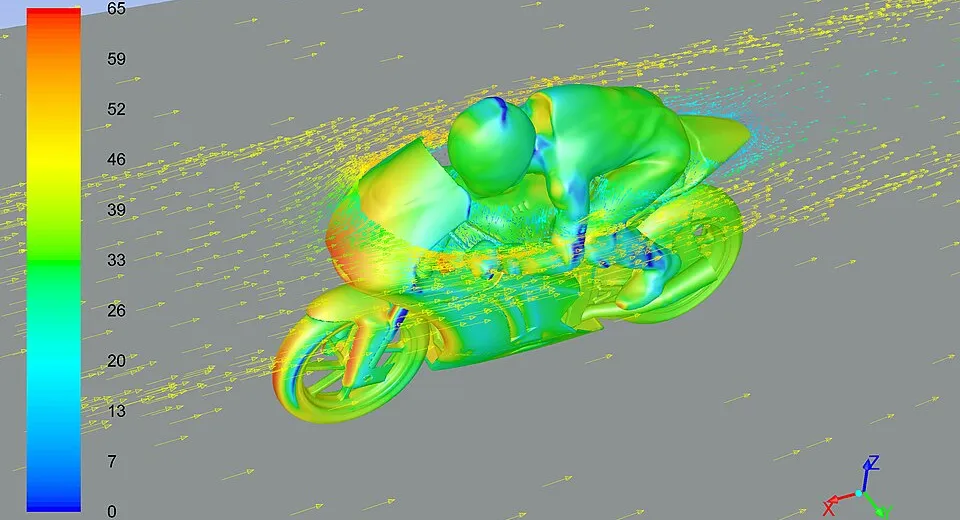
Un intero capitolo della mia tesi di laurea triennale verteva su un problema di computer grafica in ambito scientifico: mostrare una heatmap su una mesh. Nello specifico, dovevo mostrare sulla superficie di un’automobile in Autodesk Alias un gradiente di colore che interpolasse il risultato di una simulazione fluidodinamica, un qualche scalare. Pressione, velocità, , qualsiasi cosa rappresentata da un numero doveva trasformarsi in un colore sul vertice corrispondente della mesh. La classica colormap blu-verde-rosso che chiunque abbia mai aperto ParaView ha visto mille volte. Un problema decisamente standard, e ora vi racconto la mia travagliata avventura.
Vado a cercare nell’SDK di Alias come settare un colore per-vertice. Non c’è. Cerco fra gli AlShader se ce n’è uno che accetta vertex colors come input. Non c’è. Cerco su Google, su Stack Overflow, sui forum Autodesk, su tutta la documentazione raggiungibile da un essere umano nel 2024. La risposta che continua a tornare è una sola: UV unwrapping. Devi sviluppare la mesh su un piano 2D, generare una texture colorata, applicarla. Sostanzialmente, fare lo sviluppo 2D di un solido qualsiasi. Decisamente meno banale di quanto sembrasse inizialmente.
E quindi parto su quella strada. Un capitolo intero di tesi dedicato a un UV unwrap geometrico in stile xatlas: charts, packing nell’atlas, gestione dei seam, proiezione dei valori scalari sulla texture risultante, rasterizzazione dei pixel. Funziona. È brutto, fragile, complicato e tremendamente lento, ma funziona.
Un anno dopo mi sono reso conto di una cosa scomoda: avevo sbagliato proprio il problema.
La soluzione che non avevo trovato
Per visualizzare uno scalare via texture non serve nessun unwrap geometrico. Serve una texture monodimensionale, la colormap, punto. L’idea è questa:
u = scalare_normalizzato        (in [0,1])
v = 0.5 (costante, irrilevante)- Normalizzo lo scalare aerodinamico tra 0 e 1, e lo associo alla coordinata
u, e assegno una costante qualsiasi av. - Genero la texture, che è un semplice gradiente da 256x1 pixel: blu a sinistra, rosso a destra, bianco in centro, o qualsiasi scala di colore.
- Fine.
La GPU risolve il problema in modo del tutto automatico e trasparente. Interpola u fra vertici adiacenti, campiona la texture, e restituisce il gradiente di colore corretto sul triangolo. Heatmap pronta. Zero unwrap, zero seam, zero packing nell’atlas.
Nel mondo della scientific visualization questa tecnica ha un nome preciso: 1D LUT (lookup table), oppure transfer function. ParaView e OpenFOAM internamente fanno esattamente questo. È implementation detail standard, talmente standard che nessuno scrive tutorial: è il livello “cose che si imparano nei primi due giorni” se sei nell’ambiente.
La semantica u,v
Per il mio modello mentale dell’epoca, questa logica era una forzatura inaccettabile: u e v erano coordinate bidimensionali sulla superficie della mesh, un piano cartesiano che si piega in 3D. Cioè, ho sempre pensato che fossero la mappatura che associa coordinate 3D a un punto su una texture 2D, e che quindi dovessero rappresentare una mappatura continua, preservando rigorosamente la topologia della superficie. Lo sanno tutti che devono essere continue rispetto alla geometria, che vertici 3D vicini devono avere UV vicine, altrimenti la texture si distorce, si vedono cuciture, si spacca tutto. La regola è sacra e inviolabile, te la insegnano al primo corso di computer grafica, e in effetti è corretta. È la regola giusta quando si vuole applicare una superficie su una superficie.
Il punto è che non è una regola intrinseca alla matematica delle coordinate. È una regola semantica che gli abbiamo assegnato noi informatici. Le coordinate UV, in sé, sono solo due numeri per vertice. Nient’altro. La GPU non fa altro che prendere i valori (u, v) ai vertici di un triangolo, interpolarli linearmente su tutta la faccia e per ogni pixel campionare la texture alla posizione interpolata. Non ha la concezione geometrica di cosa sta interpolando, non c’è nessun vincolo che u debba essere continuo rispetto alla geometria.
Nel caso dello scalare infatti quella regola non esiste più. Due vertici adiacenti sulla mesh possono benissimo avere u=0.1 e u=0.9 se i loro valori aerodinamici sono molto diversi. È esattamente l’informazione che vogliamo mostrare. Significa che lì c’è un gradiente forte di pressione, e la GPU lo renderizza come transizione cromatica rapida.
Alla fine il concetto è lo stesso dei vertex colors, solo che il colore non viene letto da un attributo del vertice ma dedotto dal valore u tramite la texture.
Due mondi che non si parlano
La parte interessante che mi ha portato a voler scrivere questo articolo non è la tecnica in sé, che è banale, è che questa tecnica, dopo settimane di ricerca, non l’avevo trovata, perché vivevo nel mondo informatico e parlavo il linguaggio della computer grafica. In quel mondo il problema “colorare una mesh” si risolve con vertex colors, shader o UV unwrapping, ed è standard, non ci si pone seriamente la domanda di cosa fare quando queste tecniche non sono disponibili (perché non esposte dall’SDK).
Nel mondo CFD/scientifico, invece, la risposta è nota da sempre, e nessuno la documenta esplicitamente sotto forma di tutorial, perché ovvia. Però, se non hai mai aperto il codice di ParaView, se non hai mai scritto un visualizzatore custom in OpenGL, se non hai studiato la letteratura sulla scientific visualization, è invisibile.
Ci ho messo molto a decidermi di raccontarlo per davvero, mi sentivo troppo stupido, incapace di fare una query sensata su google per un problema così banale. Invece mi sono col tempo convinto che il gap fra i due ambienti generi un gap reale fra modelli mentali:
- Il modello CS pensa UV come parametrizzazione geometrica della superficie. Quindi assume che UV debba essere coerente con la geometria, e quando i vertex colors non ci sono salta direttamente al full unwrap geometrico, perché è l’unica cosa che ha senso dentro al suo paradigma.
- Il modello scientifico pensa in termini di 1D LUT e transfer function, ma non ragiona quasi mai in UV geometriche.
- La soluzione vera sta nel mezzo: usa la sintassi UV con la semantica della LUT. Nessuno dei due domini la vede in modo naturale, perché è una composizione di due pezzi che non si incontrano quasi mai nello stesso cervello.
Per controprova, un anno dopo, ho posto la stessa identica domanda a Gemini, ormai maturo, trainato su praticamente tutta la documentazione del pianeta, che mi ha dato due possibili soluzioni. La prima: bypassare il problema con OpenGL diretto, usando AlUserDraw e disegnando i triangoli a mano con glColor3f (sostanzialmente Gouraud shading scritto in casa). La seconda: UV unwrap geometrico completo, cioè esattamente il mio capitolo di tesi sbagliato. La terza opzione, quella vera, non è uscita. Quindi no, non è che cercassi male. È che il modello mentale dominante in computer grafica è così forte da rimanere dominante anche dopo essere stato ingerito da un LLM frontier. Non stupisce, avendo training set composti in larghissima parte da tutorial di game dev e tesi di computer grafica.
Se c’è una lezione che mi porto dietro da questa storia, è che certe soluzioni non sono trovabili cercandole con le parole del tuo ambiente di appartenenza. Vivono nel vocabolario di un’altra comunità, e finché non incroci qualcuno che parla entrambe le lingue, restano invisibili.
An entire chapter of my bachelor’s thesis revolved around a problem in scientific computer graphics: rendering a heatmap on a mesh. Specifically, I had to display on the surface of a car in Autodesk Alias a color gradient interpolating the result of a fluid dynamics simulation, some scalar field. Pressure, velocity, , any numerical value had to be mapped to a color on the corresponding mesh vertex. The classic blue-green-red colormap that anyone who has ever opened ParaView has seen a thousand times. A pretty standard problem. Let me tell you how that went.
I go look in the Alias SDK for how to set a per-vertex color. Not there. I check the AlShader family to see if any of them accepts vertex colors as input. Not there. I search on Google, on Stack Overflow, on the Autodesk forums, on every piece of documentation reachable by a human being in 2024. The answer that keeps coming back is always the same: UV unwrapping. You have to unfold the mesh onto a 2D plane, generate a colored texture, apply it. Essentially, unfolding an arbitrary 3D solid. Decidedly less trivial than it looked at first.
So I take that road. An entire thesis chapter dedicated to a geometric UV unwrap in xatlas style: charts, packing into the atlas, seam handling, projection of the scalar values onto the resulting texture, pixel rasterization. It works. It’s ugly, fragile, complicated and painfully slow, but it works.
A year later I realized something uncomfortable: I had been solving the wrong problem.
The solution I never found
To visualize a scalar via a texture you don’t need any geometric unwrap. You need a one-dimensional texture, the colormap, period. The idea is this:
u = normalized_scalar        (in [0,1])
v = 0.5 (constant, irrelevant)- I normalize the aerodynamic scalar between 0 and 1, assign it to the
ucoordinate, and put any constant onv. - I generate the texture, which is a simple 256x1 pixel gradient: blue on the left, red on the right, white in the middle, or any color scale.
- Done.
The GPU solves the problem completely transparently. It interpolates u between adjacent vertices, samples the texture, and returns the correct color gradient on the triangle. Heatmap ready. Zero unwrap, zero seams, zero atlas packing.
In scientific visualization this technique has a precise name: 1D LUT (lookup table), or transfer function. ParaView and OpenFOAM internally do exactly this. It’s a standard implementation detail, so standard that nobody writes tutorials about it: it’s at the “things you learn in your first two days” level if you live in that world.
The semantics of u, v
For my mental model at the time, this logic was an unacceptable stretch: u and v were two-dimensional coordinates on the surface of the mesh, a Cartesian plane bent into 3D. I had always thought of them as the mapping that associates a 3D coordinate with a point on a 2D texture, and that they therefore had to represent a continuous mapping, strictly preserving the surface topology. Everybody knows they have to be continuous with respect to the geometry, that 3D vertices close to each other must have UVs close to each other, otherwise the texture distorts, seams appear, everything breaks. The rule is sacred and inviolable, they teach it to you on the first day of any computer graphics course, and in fact it is correct. It’s the right rule when you want to apply a surface onto a surface.
The point is that it isn’t a rule intrinsic to the mathematics of the coordinates. It’s a semantic rule we computer scientists assigned to them. UV coordinates, in themselves, are just two numbers per vertex. Nothing more. The GPU does nothing but take the (u, v) values at the vertices of a triangle, interpolate them linearly across the whole face, and for each pixel sample the texture at the interpolated position. It has no geometric notion of what it’s interpolating, there is no constraint at all that u must be continuous with respect to the geometry.
In the scalar case that rule simply doesn’t exist anymore. Two adjacent vertices on the mesh can perfectly well have u=0.1 and u=0.9 if their aerodynamic values are very different. That’s exactly the information we want to show. It means there’s a strong pressure gradient at that point, and the GPU renders it as a fast color transition.
In the end the concept is the same as vertex colors, except the color is not read from a vertex attribute but derived from the value of u through the texture.
Two worlds that don’t talk to each other
The interesting part, the one that pushed me to actually write this article, isn’t the technique itself, which is trivial. It’s that this technique, after weeks of searching, I had never found, because I was living in the computer-science world and speaking the language of computer graphics. In that world the problem “color a mesh” is solved with vertex colors, shaders or UV unwrapping, and it’s standard, nobody seriously asks themselves what to do when those techniques aren’t available (because they’re not exposed by the SDK).
In the CFD/scientific world, on the other hand, the answer has been known forever, and nobody documents it explicitly as a tutorial, because it’s obvious. But if you’ve never opened the ParaView source, if you’ve never written a custom OpenGL visualizer, if you’ve never studied the scientific visualization literature, it’s invisible.
It took me a long time to bring myself to tell this story out loud, I felt too stupid, incapable of writing a sensible Google query for such a trivial problem. Over time I convinced myself that the gap between the two environments produces a real gap between mental models:
- The CS model thinks of UV as a geometric parametrization of the surface. So it assumes UV must be coherent with the geometry, and when vertex colors aren’t available it jumps straight to a full geometric unwrap, because that’s the only thing that makes sense inside its paradigm.
- The scientific model thinks in terms of 1D LUT and transfer functions, but almost never reasons in geometric UV.
- The actual solution lives in the middle: it uses the syntax of UV with the semantics of a LUT. Neither domain sees it naturally, because it’s a composition of two pieces that almost never meet within the same mind.
To prove my point, a year later, I asked the exact same question to Gemini, now mature, trained on basically all the documentation on the planet, and it gave me two possible solutions. The first: bypass the problem with raw OpenGL, using AlUserDraw and drawing the triangles by hand with glColor3f (essentially Gouraud shading written from scratch). The second: full geometric UV unwrap, that is, exactly my wrong thesis chapter. The third option, the real one, didn’t come up. So no, it wasn’t that I was searching badly. It’s that the dominant mental model in computer graphics is so strong that it stays dominant even after being ingested by a frontier LLM. Not surprising, given that the training set is composed largely of game-dev tutorials and computer graphics theses.
If there’s one lesson I carry with me from this story, it’s that certain solutions can’t be found by searching for them with the words of your own community. They live in the vocabulary of another community, and until you bump into someone who speaks both languages, they stay invisible.
Note: this article was automatically translated from Italian by AI.